Recumbent vehicle drivetrain
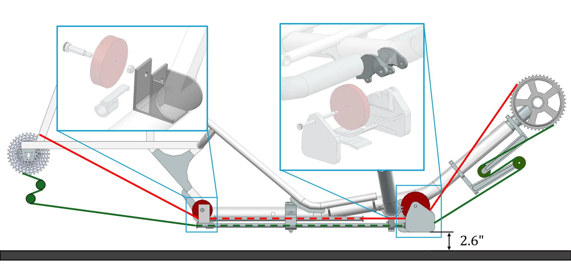
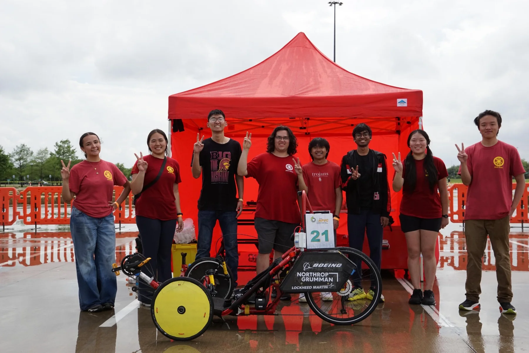
I led drivetrain design for USC’s electric-assist recumbent: routing the chain from the front crank to the rear wheel, under the rider, with as little friction as possible, while clearing the rider, the frame and the road. The team took 1st place in design at the ASME e-HPVC in 2025 and 2026.
The drivetrain
My role
As drivetrain lead, I designed how the chain gets from the pedals to the rear wheel: choosing the path, the idlers and the mounts. As vice president, I coordinate 20 engineers across the drivetrain, mechanical and electrical subsystems.
Requirements
A bike drivetrain has two pass-or-fail requirements, clearance around the rider and the bike, and clearance off the ground, plus one to optimize: minimal power loss without the chain derailing.
Roller-chain losses come from four places. Links rubbing as they wrap onto a sprocket, which grows with wrap angle and shrinks with bigger sprockets. Impact as rollers mesh with teeth. Vibration, which drops as chain tension rises. And friction between the chain walls and sprocket teeth, which grows with the chain’s lateral angle. That angle also causes derailment: chains start jumping at 6°, and 2.5°, the typical maximum on an upright bike’s derailleur, is the practical limit.
| Requirement | Target | Result |
|---|---|---|
| Rider and part clearance | No interference with the rider’s legs or other subsystems | Met |
| Ground clearance | 2.5″: the 1.97″ competition speed bump plus 0.53″ for tire deflection | 2.6″ |
| Max lateral chain angle | Under 2.5° | 1.9° |
Trade study
I generated design variants by drawing different tension-line paths through the frame. Every variant stacked the tension and slack lines vertically, which keeps the lateral angle low. Three variants cleared both pass-or-fail requirements, so I scored them against the remaining criteria: +1 better than the average of the other two, −1 worse, 0 average.
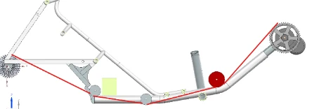 V1
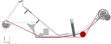 V2
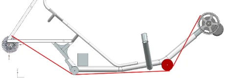 V3, selected
| Criterion | V1 | V2 | V3 |
|---|---|---|---|
| Total chain wrap angle | +1 | 0 | 0 |
| Weight (number of idlers) | −1 | 0 | 0 |
| Sprocket contacts (number of idlers) | −1 | 0 | 0 |
| Moving the battery: forward center of gravity, front-tip risk | 0 | −1 | 0 |
| Moving the battery: mesh-seat clearance | 0 | −1 | 0 |
| Max lateral angle off the cassette | 0 | +1 | 0 |
| Total | −1 | −1 | 0 |
V3 required the fewest compromises. V1 wrapped the chain best but needed more idlers, adding weight and sprocket contacts. V2 needed the battery moved forward, which shifts the center of gravity toward a forward tip and presses the battery into the mesh seat.
Final design
- Chain pathVertically stacked tension and slack lines, giving a 1.9° max lateral chain angle. The lowest point sits 2.6″ off the ground.
- IdlersTwo on the tension line. A large 23-tooth, 99 mm idler at the front bend keeps link articulation and friction low. A 15-tooth, 70 mm idler at the rear clears the battery. The slack line runs over one curved guide.
- Chain tubesA tube in the middle of each line stops the chain sagging: two mounting points on the tension tube, three on the slack tube.
- TensionerA commercial chain tensioner on the slack line takes up slack when the pedal boom is adjusted for riders from 5′4″ to 6′3″.
- MountsBoth idler mounts are structure, not just brackets. The front mount is a gusset between the main crossmember and the main spar. The rear mount is the end cap of the main spar.
Frame integration and FEA
Pedaling loads the frame in two opposing ways, so each was run as its own worst case in FEA. In the chain-tension case, the maximum chain tension before the rear wheel breaks traction acts along the chain line from the chainring to the first idler. In the leg case, a 200 lbf single-leg press acts along the line from the rider’s hip to the pedal tube.
Both are cyclic, so the allowable stress comes from fatigue: 300 pedal revolutions per km over a 50 km race, times 5 for ten hours of pre-competition testing, gives 7.5 × 10⁴ cycles and an allowable 87.9 MPa from the S-N curve for welded aluminum joints.
The first results showed the frame would not survive. Building the drivetrain’s front idler mount into the frame, as a gusset between the main spar and the main crossmember, fixed it.
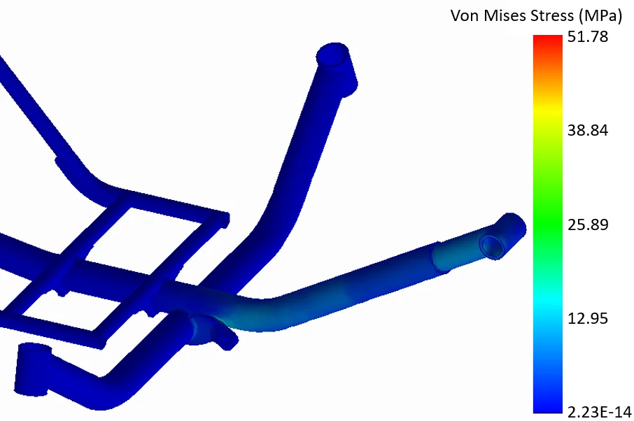
| Load case | Peak stress | Allowable (fatigue) | Factor of safety | Max displacement |
|---|---|---|---|---|
| Chain tension | 51.78 MPa | 87.9 MPa | 1.70 | 0.656 mm |
| Leg press, 200 lbf | 40.87 MPa | 87.9 MPa | 2.15 | 1.254 mm |
Displacements this small don’t affect the rider’s pedaling.
Test stand
The team’s modular drivetrain test stand mounts components in a working mockup before the real system is built, and measures power consumption from the drive motor’s voltage and current. Its 2025 test found that static chain tubes and a low-friction guide consumed the same power as an idler-only drivetrain, even though they were expected to add friction. That result is why this design can use tubes and a guide to route the chain low under the seat with no loss of efficiency. The stand’s frame was reused this year with new mounts for this year’s components.
Manufacturing
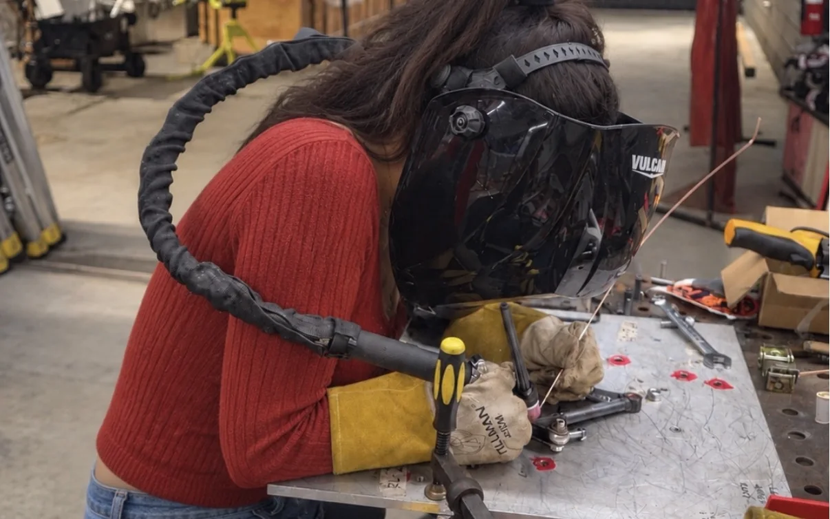
We built the drivetrain in-house: machined idlers, MIG and TIG welded mounts, and composite parts laid up by the team.
What’s next
The vehicle’s new telemetry system will record drag-race data, which the team plans to use to optimize the drivetrain’s gear ratios.