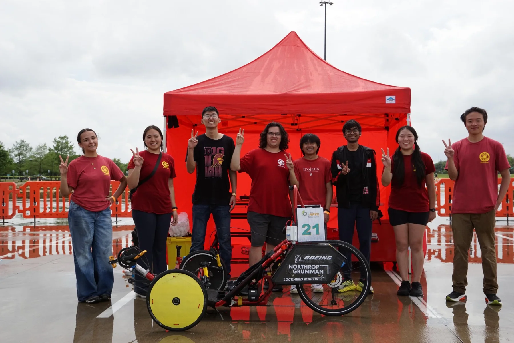
Recumbent vehicle drivetrain
Drivetrain design for USC’s entry in the ASME Human Powered Vehicle Challenge: aluminum idlers modeled in CAD, checked with FEA on the key load cases, and built in-house by machining, MIG/TIG welding and composite layup.
Take it apart
Spin the idler on its axle or pull the assembly apart to see the bracket, bearings and axle.
Simplified stand-in geometry. The exported CAD assembly replaces it once it’s ready.
My role
I lead drivetrain design and, as vice president, coordinate 20 engineers across the drivetrain, mechanical and electrical subsystems through to national competition. In my first year I also designed the vehicle’s telemetry PCB in KiCad.
Victoria: the drivetrain layout (gear range, chain path, why idlers), and the decisions you made versus the team.
Design and analysis
I modeled the aluminum idlers in CAD and ran FEA on the key load cases before committing to manufacture.
Victoria: which load cases, the resulting stress and safety factor, and any mass you saved.
Manufacturing
We built the drivetrain in-house: machined idlers, MIG and TIG welded mounts, and composite parts laid up by the team.
Victoria: photos from the shop and the competition, and what you would change next year.